Lær om L298N Motor driver og L293D Motor shield
In this tutorial, we will learn about the L298N motor driver and the L293D motor shield. These are widely used for motor-related Arduino projects.
Table of Contents
- Exploring Motor Control: L298N vs L293D for Arduino
- L298N Motor Driver
- DC Motors:
- Stepper Motors:
- Brushless DC (BLDC) Motors:
- Geared Motors:
- Unipolar Stepper Motors:
- Bipolar Stepper Motors:
- Universal Motors:
- Servo Motors (Not Directly):
- Induction Motors (Not Directly):
- Parts of the L298N motor driver
- Outputs of the L298N Motor Driver
- Key aspects of the L298N Motor Driver
- Dual H-Bridge Configuration
- What is a Dual H-Bridge Configuration?
- Current Handling
- PWM Control
- What is PWM control?
- Heat Dissipation
- L293D Motor Shield
- DC Motors:
- Stepper Motors:
- Servo Motors (Limited):
- Geared Motors:
- Unipolar Stepper Motors (Limited):
- Bipolar Stepper Motors (Limited):
- Universal Motors (Limited):
- Induction Motors (Not Directly):
- Parts of the L293D Motor Shield
- Outputs of the L293D Motor Shield
- Differences and Considerations
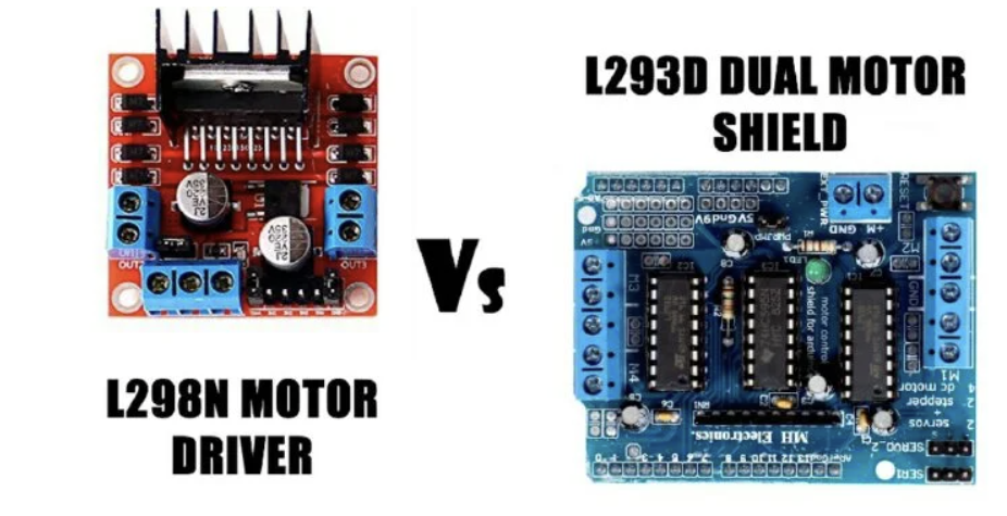
Exploring Motor Control: L298N vs L293D for Arduino
When it comes to motor control in Arduino projects, two popular modules stand out: the L298N Motor Driver and the L293D Motor Shield. In this article, we’ll delve into the features, applications, and differences between these modules to help you make an informed choice for your next project.
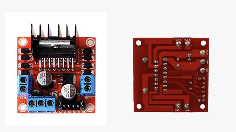
L298N Motor Driver
The L298N Motor Driver is a popular integrated circuit (IC) designed for controlling and driving DC motors and bipolar stepper motors. Manufactured by STMicroelectronics, the L298N serves as a versatile and efficient motor driver, widely used in robotics, automation, and various electronic projects.
Key features of the L298N Motor Driver include dual H-bridge capability, allowing it to control two motors independently or drive a single motor bidirectionally. This makes it suitable for applications requiring precise motor control, such as speed and direction adjustments. The IC can handle a wide range of motor voltages, typically up to 46V, making it compatible with various motor types and power requirements.
The L298N incorporates built-in protection features like overtemperature and overcurrent protection, enhancing the reliability of the connected motors and the overall system. Additionally, the IC is designed with logic inputs that facilitate straightforward interfacing with microcontrollers, enabling seamless integration into electronic projects.
Overall, the L298N Motor Driver is a versatile and reliable choice for motor control applications, providing a cost-effective and efficient solution for hobbyists, students, and engineers working on projects involving motorized systems.
The L298N motor driver is a versatile dual H-bridge motor driver integrated circuit that can handle various types of motors. Here are the types of motors that can be connected to the L298N motor driver
1. DC Motors:
- Description: DC (Direct Current) motors are the most common type used with the L298N motor driver. They come in various sizes and configurations.
- Connection: The L298N can drive two DC motors bidirectionally, allowing forward, backward, and stop movements.
2. Stepper Motors:
- Description: Stepper motors are used in applications where precise control over rotation is required. They move in discrete steps.
- Connection: The L298N can control one stepper motor. It requires four input signals (two per coil) for proper operation.
3. Brushless DC (BLDC) Motors:
- Description: BLDC motors are commonly used in applications requiring higher efficiency and longer lifespan. They operate using electronic commutation.
- Connection: While the L298N is not specifically designed for BLDC motors, it can be used for simple speed control in certain configurations. However, dedicated BLDC motor drivers are more suitable for advanced control.
4. Geared Motors:
- Description: Geared motors have an integrated gearbox to reduce speed and increase torque. They are useful in applications requiring higher torque at lower speeds.
- Connection: Geared DC motors can be connected to the L298N in the same way as standard DC motors.
5. Unipolar Stepper Motors:
- Description: Unipolar stepper motors have two windings per phase and a center tap for each winding. They are commonly used in hobbyist projects.
- Connection: The L298N is not optimized for unipolar stepper motors, but it can be adapted for use by connecting the center taps appropriately.
6. Bipolar Stepper Motors:
- Description: Bipolar stepper motors have two windings per phase without a center tap. They are widely used in applications requiring precise control.
- Connection: The L298N is suitable for controlling one bipolar stepper motor, and it requires the proper connection of the motor’s coils.
7. Universal Motors:
- Description: Universal motors are versatile and can run on both AC and DC power. They are commonly found in household appliances.
- Connection: The L298N is designed for DC motor control and is not suitable for universal motors operating on AC power.
8. Servo Motors (Not Directly):
- Description: Servo motors are commonly used for precise angular control. However, they typically have their own control circuitry.
- Connection: The L298N is not designed for direct servo motor control. Servos are usually controlled using PWM signals directly from a microcontroller.
9. Induction Motors (Not Directly):
- Description: Induction motors are commonly used in industrial applications. They require specialized motor drivers for control.
- Connection: The L298N is not suitable for directly driving induction motors.
Understanding the types of motors compatible with the L298N motor driver helps in selecting the appropriate motor for a given project and ensures proper control and functionality.
Parts of the L298N motor driver
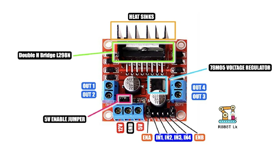
- H-Bridge Circuitry:
- The L298N features a dual H-bridge configuration, allowing it to control two motors independently. The H-bridge circuitry consists of four power transistors or MOSFETs arranged in the shape of an ‘H.’
- Input Pins:
- The L298N typically has input pins for each motor, labeled as IN1, IN2, IN3, and IN4. These pins receive control signals to determine the direction and speed of the connected motors.
- Power Supply Pins:
- VS (Motor Supply Voltage): This pin is connected to the external power supply that provides power to the motors. The voltage range depends on the motor specifications.
- VSS (Chip Supply Voltage): This pin is connected to a separate power supply that provides power to the internal logic of the L298N. It is often connected to the Arduino’s 5V output.
- Ground Pins:
- GND: Connected to the ground of the external power supply.
- GND (Logic Ground): Connected to the ground of the logic circuit (Arduino).
- Enable Pins:
- ENA and ENB: These are enable pins for Motor A and Motor B, respectively. By providing a PWM signal to these pins, the speed of the motors can be controlled.
- Output Pins:
- OUT1, OUT2, OUT3, OUT4: These pins are connected to the terminals of the motors. The direction and speed of the motors are controlled by the logic signals applied to the input pins.
- Built-in Diodes:
- The L298N incorporates built-in diodes (flyback diodes) to protect against voltage spikes that occur when the motor is turned off.
Outputs of the L298N Motor Driver
- Direction Control:
- The L298N allows control over the direction of the motors. By configuring the input signals appropriately (changing the states of IN1, IN2, IN3, and IN4), the motors can move forward, backward, or stop.
- Speed Control:
- Speed control is achieved by providing a PWM (Pulse Width Modulation) signal to the enable pins (ENA and ENB). The duty cycle of the PWM signal determines the speed of the connected motors.
- Current Handling:
- The L298N can handle a significant amount of current (up to 2A per channel) for driving motors. This makes it suitable for applications requiring higher power.
- Dual Motor Control:
- The dual H-bridge configuration allows for the independent control of two motors, making it versatile for robotics and mechatronics projects.
- Versatility:
- The L298N is compatible with various motor types, including DC motors and stepper motors. This versatility makes it widely used in different applications.
Understanding the parts and outputs of the L298N motor driver is crucial for effectively incorporating it into motor control projects, offering flexibility and precise control over connected motors.
Key aspects of the L298N Motor Driver
The L298N is a robust and versatile motor driver that provides efficient control for DC motors and stepper motors. Here are some key aspects of the L298N.
Dual H-Bridge Configuration
The L298N boasts a dual H-bridge design, enabling independent control of two motors. This makes it ideal for applications requiring the precise management of multiple motors.
What is a Dual H-Bridge Configuration?
A dual H-bridge configuration refers to a design in electronics, particularly in motor driver circuits. The term “H-bridge” describes the arrangement of switches or transistors that form the shape of the letter ‘H’ when connected. A dual H-bridge configuration specifically involves two separate H-bridges within the same circuit.
- H-Bridge:- An H-bridge is a circuit topology that allows for the control of a motor’s direction and speed by managing the polarity of the applied voltage. It typically consists of four switching elements (transistors or MOSFETs) arranged in the shape of an ‘H.’ The motor is connected at the center of the ‘H.’ The four switches are paired to form two sides of the ‘H.’ When one side is activated, the motor turns in one direction; when the other side is activated, the motor turns in the opposite direction.
- Dual H-Bridge Configuration:- In a dual H-bridge configuration, there are two independent H-bridges within the same circuit. This setup allows for the control of two motors independently, enabling precise control over the direction and speed of each motor. It is commonly used in robotics and mechatronics applications where multiple motors need to be controlled separately.
- Application:- Dual H-bridge configurations are frequently employed in scenarios where dynamic and independent control of two motors is essential. For example, in a robotic vehicle, each wheel may be connected to a separate H-bridge, allowing the robot to move in any direction by controlling the speed and direction of each wheel individually.
- Control Signals:- To control the dual H-bridge, digital signals are sent to the input pins corresponding to each of the four switches. By manipulating the states of these input signals, the direction and speed of the connected motors can be managed. In summary, a dual H-bridge configuration provides a versatile solution for controlling multiple motors in robotics and automation projects, offering independent control over each motor’s movement.
Current Handling
With a current handling capacity of up to 2A per channel, the L298N is well-suited for projects demanding higher power and torque from motors. This makes it suitable for a variety of applications, from robotics to vehicle prototypes.
PWM Control
The L298N supports Pulse Width Modulation (PWM) control, enabling users to regulate the speed of connected motors. This feature adds versatility to the motor control, especially in applications where variable speeds are essential.
What is PWM control?
PWM, which stands for Pulse Width Modulation, is a technique used to control the average voltage or power supplied to an electronic device. It is commonly employed in electronics to control the speed of motors, the brightness of LEDs, and other parameters in a wide range of applications. Here’s an overview of PWM control
- Pulse Width Modulation (PWM):- PWM is a method of digitally encoding analog signals. It involves generating a series of pulses with varying widths (duty cycles) within a fixed period.
- Duty Cycle:- The duty cycle is the ratio of the pulse duration to the total time of one cycle. It is expressed as a percentage and determines the average power delivered to the load.
- Frequency:- PWM signals have a fixed frequency, representing the rate at which the pulses are repeated in one second.
How PWM Control Works
- Motor Speed Control:- In motor control applications, PWM is commonly used to control the speed of DC motors. By varying the duty cycle of the PWM signal, the average voltage applied to the motor terminals changes, influencing the motor speed.
- LED Brightness Control:- PWM is used for dimming LEDs. A higher duty cycle results in brighter light, while a lower duty cycle reduces brightness. The rapid switching of the LED on and off at a high frequency makes the change in brightness imperceptible to the human eye.
- Voltage Regulation:- PWM is employed in voltage regulation circuits to control the average output voltage. By adjusting the duty cycle, the average voltage supplied to the load can be regulated.
- Audio Signal Generation:- PWM is used in audio applications to generate analog-like signals by rapidly switching between high and low states. In digital audio systems, PWM signals are converted to analog using a low-pass filter.
- Temperature Control:- PWM is applied in temperature control systems to regulate the power supplied to a heating element. By adjusting the duty cycle, the average power and, consequently, the temperature can be controlled.
Advantages of PWM Control
- Efficiency:- PWM allows for efficient power control, minimizing energy losses.
- Precision:- It provides precise control over devices, allowing for fine adjustments.
- Digital Interface:- PWM signals are generated using digital circuitry, making them compatible with digital systems and microcontrollers.
- Versatility:- PWM is versatile and widely applicable in various electronic control systems. In summary, PWM control is a versatile and widely used technique for modulating the average power delivered to electronic devices. Its ability to efficiently control motors, LEDs, and other components makes it a fundamental tool in electronics and automation.
Heat Dissipation
Given its potential for higher current flow, the L298N may generate heat during extended operation. To address this, external heat sinks can be added to ensure optimal performance and longevity.
L293D Motor Shield
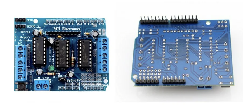
The L293D Motor Shield is a popular motor driver shield designed for use with Arduino boards. It simplifies motor control by providing an easy interface between the Arduino and motors. It provides an easy interface for controlling DC motors and stepper motors. Here are the types of motors that can be connected to the L293D Motor Shield
1. DC Motors:
- Description: DC (Direct Current) motors are the most common type of motor compatible with the L293D Motor Shield. They come in various sizes and configurations.
- Connection: The L293D can drive two DC motors bidirectionally, allowing for forward, backward, and stop movements.
2. Stepper Motors:
- Description: Stepper motors are used when precise control over rotation is required. They move in discrete steps.
- Connection: The L293D Motor Shield can control one stepper motor. It requires four input signals (two per coil) for proper operation.
3. Servo Motors (Limited):
- Description: Servo motors are used for precise angular control. However, the L293D Motor Shield is not specifically designed for servo motor control.
- Connection: While the shield may offer limited support for servo motors, it’s generally more common to use dedicated servo motor control circuits.
4. Geared Motors:
- Description: Geared motors have an integrated gearbox to reduce speed and increase torque. They are suitable for applications requiring higher torque at lower speeds.
- Connection: Geared DC motors can be connected to the L293D Motor Shield in the same way as standard DC motors.
5. Unipolar Stepper Motors (Limited):
- Description: Unipolar stepper motors have two windings per phase and a center tap for each winding. They are commonly used in hobbyist projects.
- Connection: The L293D Motor Shield is not optimized for unipolar stepper motors, but with proper wiring adaptations, it may be used.
6. Bipolar Stepper Motors (Limited):
- Description: Bipolar stepper motors have two windings per phase without a center tap. They are commonly used in applications requiring precise control.
- Connection: The L293D Motor Shield can control one bipolar stepper motor with the proper connection of the motor’s coils.
7. Universal Motors (Limited):
- Description: Universal motors can run on both AC and DC power. However, the L293D Motor Shield is designed for DC motor control.
- Connection: While the shield may offer limited compatibility, universal motors are typically controlled using other methods.
8. Induction Motors (Not Directly):
- Description: Induction motors are commonly used in industrial applications. They require specialized motor drivers for control.
- Connection: The L293D Motor Shield is not suitable for directly driving induction motors.
Understanding the types of motors compatible with the L293D Motor Shield helps in selecting the appropriate motor for a given Arduino project and ensures proper control and functionality. Keep in mind that while the shield supports various motor types, it may have limitations in certain applications.
Parts of the L293D Motor Shield
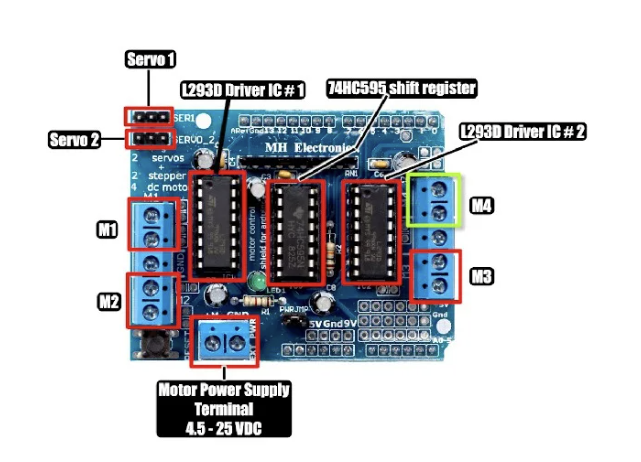
- L293D Motor Driver IC:
- The heart of the motor shield is the L293D IC. It is a dual H-bridge motor driver, capable of driving two DC motors bidirectionally or one stepper motor.
- Screw Terminals:
- The shield usually has screw terminals for connecting the wires from the motors. These terminals provide a secure and easy-to-use connection.
- Motor Output Pins:
- There are typically output pins labeled M1, M2, M3, and M4, representing Motor 1, Motor 2, Motor 3, and Motor 4. These pins are where you connect the wires leading to the motors.
- Power Input Pins:
- PWRIN and GND: These pins are used to connect an external power source to power the motors. They are separate from the Arduino’s power supply.
- 5V Power Source Selector:
- There might be a jumper or switch to select the power source for the internal logic of the shield, either from the Arduino (5V) or an external source.
- Motor Voltage Selector Jumper:
- Some shields have a jumper to select the motor voltage, allowing compatibility with different motor types.
- External Power Indicator LED:
- An indicator LED may be present to show when an external power source is selected.
- Logic Voltage Indicator LED:
- Another LED might indicate when the logic voltage is provided by the Arduino.
- Arduino Pins Breakout:
- The shield exposes some of the Arduino pins, allowing for easy connection of other sensors or modules.
Outputs of the L293D Motor Shield
- Bidirectional Motor Control:
- The L293D can drive two DC motors bidirectionally. By controlling the input signals to the motor driver IC, the motors can move forward, backward, or stop.
- Stepper Motor Control:
- It supports the control of one stepper motor. Stepper motors are commonly used in applications requiring precise control, such as robotics.
- Current Sensing:
- Some versions of the shield may include current-sensing resistors to monitor the current drawn by the motors.
- Logical Voltage Control:
- The shield allows the Arduino to control the logic voltage supplied to the L293D IC, providing flexibility in interfacing with different microcontrollers.
- Easy Connection:
- The screw terminals and labeled motor output pins simplify the process of connecting and controlling motors without extensive wiring.
- Versatility:
- The L293D Motor Shield is versatile and suitable for various motor-driven projects, making it a popular choice among hobbyists and enthusiasts.
Differences and Considerations
- Current Handling:
- L298N: Higher current handling (up to 2A), suitable for high-power applications.
- L293D: Lower current handling (around 0.6A per bridge), suitable for small to medium-sized projects.
- Voltage Range:
- L298N: Supports a wider voltage range (up to 46V).
- L293D: Designed for lower voltage applications (up to 25V).
- Integration:
- L298N: A standalone module, requires wiring.
- L293D: Designed to fit directly onto an Arduino for easy integration.
- Heat Dissipation:
- L298N: May require external heat sinks for prolonged use.
- L293D: Generally generates less heat, suitable for projects with lower current requirements.